CT and X-ray review
Internal defects, voids, geometry, and hidden features can be reviewed with clearer spatial context when teams need to understand location, depth, and relation to the full part.
Solutions / Spatial 3D / Industrial
Inspection teams often work with 3D structures, hidden defects, and internal geometry, but still make decisions through a flat review experience that slows interpretation and explanation.
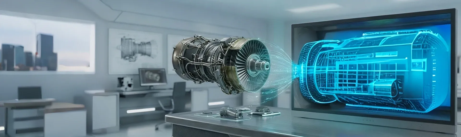
Glasses-free 3D helps teams read CT, X-ray, NDT, and internal assembly data with visible depth on screen, without adding headsets, glasses, or a separate immersive workflow at the station. It is especially useful in autostereoscopic industrial inspection scenarios where teams need to explain hidden geometry quickly.
Common Uses
Internal defects, voids, geometry, and hidden features can be reviewed with clearer spatial context when teams need to understand location, depth, and relation to the full part.
Crack orientation, defect spread, and internal structure are easier to interpret when the review process does not depend entirely on switching across many flat views.
Stacked components, hidden features, package structure, and internal alignment can be checked with more immediate spatial understanding.
Review teams can examine how a defect relates to surrounding structure when root cause work needs more than a surface-level visual explanation.
Inspection findings can be explained more clearly across QA, engineering, operations, suppliers, or customers when the screen itself communicates structure more directly.
New inspectors and cross-functional reviewers benefit when complex internal conditions can be understood faster during guided review.
Detailed View
The strongest fit is usually not generic 3D content. It is a review task where teams repeatedly need to judge hidden structure, explain defect location, or align multiple functions around the same finding.
When the object of interest is inside a part, teams spend time reconstructing depth from many slices or view states. A better spatial display can reduce that interpretation burden and make review more direct.
Inspection is rarely the last step. Findings often move into engineering, quality, operations, or supplier conversations, so a display that makes structure easier to read can improve downstream alignment.
A useful solution has to fit the real inspection environment. That means considering viewing distance, lighting, operator position, and how often teams move between conventional screens and spatial review.
Why Teams Evaluate It
What Good Deployment Starts With
Primary use
Start with the inspection task where spatial judgment matters most: CT review, NDT analysis, electronics inspection, failure analysis, or communication of findings.
Data path
Confirm how CT, X-ray, ultrasound, AOI, or other imaging output reaches the display in the current toolchain, and whether the workflow depends on specific software or exported assets.
Workstation fit
Check station layout, ambient light, viewing distance, and how often operators move between standard 2D review and spatial inspection modes.
Decision point
Define what better means for the team: faster interpretation, fewer review loops, clearer communication, or better training transfer. That makes evaluation more concrete.
Next Step
Start with the industrial review task where hidden structure is hardest to judge on a flat screen. Then test the display with your own data, your current software path, and the actual station conditions your team works in.
Cookie Consent
You can update consent any time. Details live in our Privacy Policy and Cookie Policy.
Cookie Preferences
Essential cookies are always active. More detail is available in the policy pages.
Required for site function, consent storage, and security.