
Stereoscopic 3D Images: Technical Explainer
Stereoscopic 3D images are paired left-eye and right-eye views packaged into a single file or signal so a display can present depth without inferring it from a flat picture. For professional review teams evaluating glasses-free 3D spatial display systems, understanding how stereoscopic 3D images are built and delivered is the starting point for deciding whether the format fits the workflow.
This explainer focuses on the image side of the format: what a stereoscopic image actually contains, how it is produced, how it is delivered, and how it lines up with autostereoscopic display workflows used on current 3DV Spatial Display systems. It is written for buyers and technical evaluators, not for general consumer entertainment contexts.
A stereoscopic 3D image stores two views in one file so depth can be delivered without glasses.
What stereoscopic 3D images are and how they differ from regular images
A regular 2D image stores a single view of a scene. A stereoscopic 3D image stores two views that correspond to the slight horizontal offset between a viewer’s left and right eyes. When the display shows the correct view to each eye, the brain combines them into a depth percept.
Common packaging conventions include:
- Side-by-side (SBS). Left and right views stored left-to-right in one frame. Half-width SBS keeps the original vertical resolution; full-width SBS keeps the original horizontal resolution.
- Top-and-bottom (over-under). Left view stacked above right view in one frame.
- Interlaced or column-/row-interleaved. Views woven into alternating columns or rows, depending on the optical layer.
- Separate left and right files. Two distinct files played or processed in lockstep.
The file is not automatically a stereoscopic image just because it is wide or 3D-looking. The display, the player, or the renderer must know which pixels belong to which eye, and must be able to route each view to the correct eye.
How stereoscopic 3D images are produced and prepared
Production paths vary, but each must end with two correctly aligned views.
- Stereo camera rigs. Two cameras mounted at roughly interocular distance, mechanically aligned and color-matched. Used in narrative, microscopy, and industrial capture where physical parallax is meaningful.
- Render pipelines. 3D applications export two camera passes from a virtual scene. CAD viewers, DICOM viewers with stereo output, and engines such as Unity or Unreal commonly generate stereoscopic 3D image pairs from the same scene.
- Depth-based synthesis. A 2D image plus a depth map is used to generate a second view. Quality depends on depth-map accuracy and edge handling.
- Multi-view stitching. Several overlapping images are combined to produce left and right views, often used in microscopy and inspection.
For professional teams, the relevant question is whether the source tool can export a known, labeled stereo pair rather than relying on automatic conversion after the fact. Pairs that are exported under controlled conditions are easier to align, color-match, and validate against downstream display expectations.
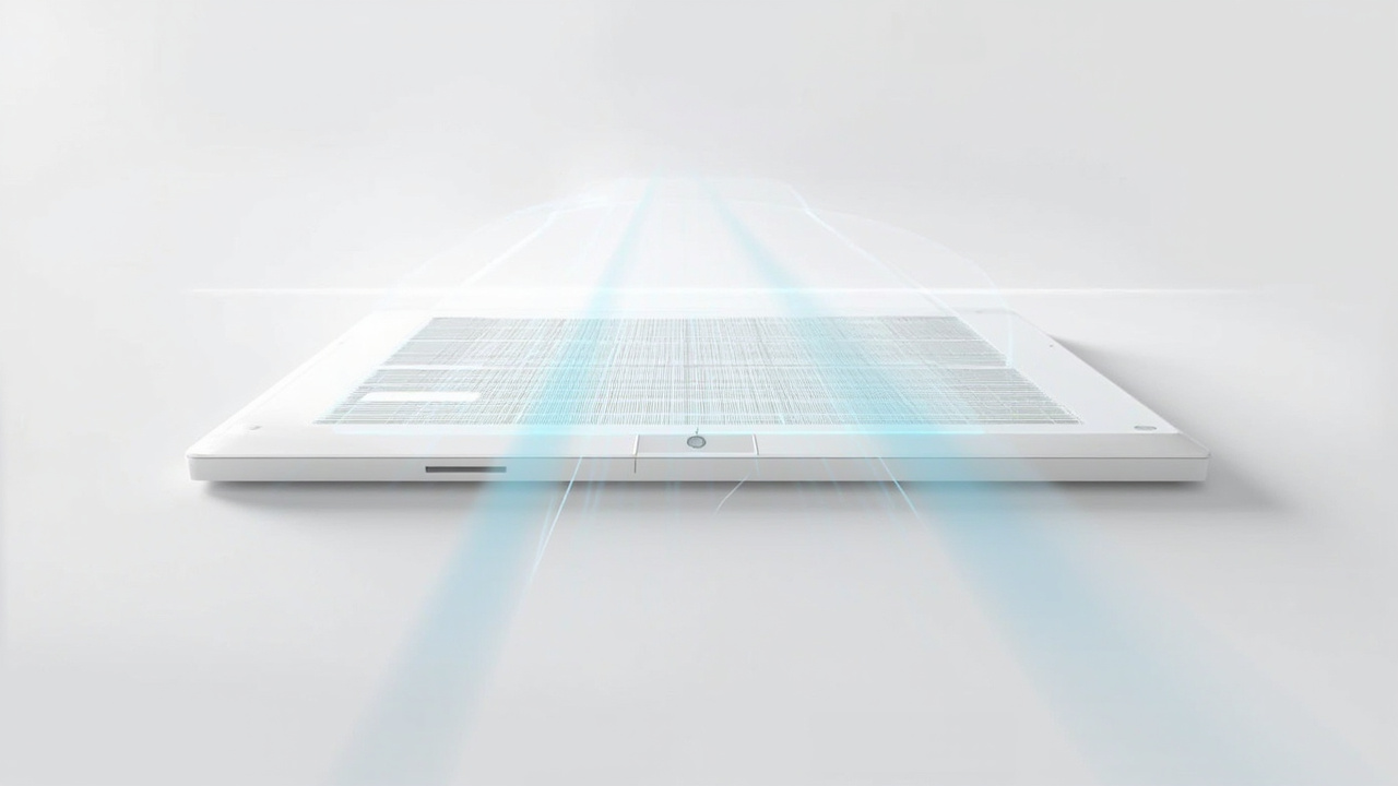
Autostereoscopic displays separate the left and right views using an optical layer and eye tracking, not glasses.
Delivery methods: glasses-based, head-mounted, and glasses-free
The same pair of views can reach the viewer through different delivery systems, and each system imposes different requirements on the image file.
- Anaglyph and polarized glasses. Two views are encoded into one frame using color or polarization filters. The viewer’s glasses separate them. Image-side requirements differ, but a single file is still the input.
- Active-shutter and head-mounted displays. Synchronized shutters or independent displays per eye, with the image file or stream carrying both views plus timing information.
- Glasses-free autostereoscopic displays. An optical layer such as a lenticular lens array or parallax barrier directs interleaved views to the correct eye. The display, not the user, handles separation.
Glasses-free delivery is the model used by 3DV Spatial Display systems. From the image’s point of view, the format is similar to other stereoscopic workflows: a stereo pair must reach the display, and the display then maps each view to the appropriate eye. The difference is that the viewer does not need to wear or sync anything.
How autostereoscopic displays render stereoscopic images for the viewer
On an autostereoscopic display, the input image is split so that left-eye pixels reach the left eye and right-eye pixels reach the right eye. In practice this involves several cooperating stages.
- Eye tracking. Structured-light sensors or camera-based tracking locate the viewer’s eyes relative to the screen.
- View mapping. The display calculates which subpixels or microlens directions will reach each eye from the current head position.
- Dynamic mapping. As the viewer moves, the mapping updates so the correct view stays routed to the correct eye.
- Display-side processing. FPGA or display-side logic reshapes the incoming stereoscopic image in real time, often without burdening the host system.
- 2D / 3D switching. On Pro models, the display can switch between a high-quality 2D presentation and a 3D presentation of the same input, which is useful when the workflow mixes regular reference images with stereoscopic review.
Because mapping is dynamic, a stereoscopic image prepared for one viewing position still works for a viewer who leans or shifts, within the design range of the specific model. Teams that need multiple viewers to see correct depth simultaneously should review how a given model handles multi-viewer scenarios before relying on group review.
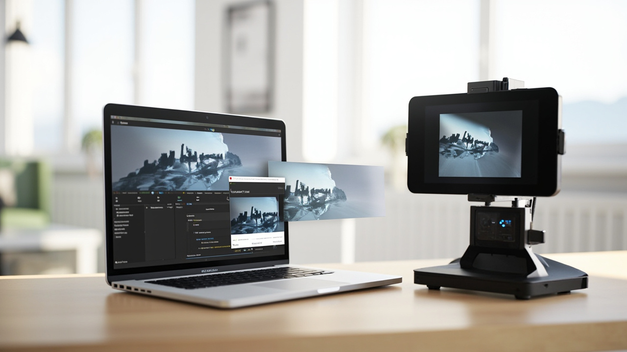
A typical stereoscopic image workflow moves from source export to validation to review on the chosen Spatial Display model.
Workflow fit: where stereoscopic 3D images add value
Stereoscopic 3D images are not a general-purpose upgrade for every image. They add the most value where the underlying scene or model already has meaningful depth and where the review task depends on that depth being visible.
Workflow areas where stereoscopic image content tends to fit well:
- Medical visualization. Stereo renderings of volumetric data, anatomical models, and surgical planning visuals where depth carries clinical review meaning.
- Industrial inspection and NDT. Stereo captures of components, CT-derived visuals, and stereo pairs that help reviewers separate layers and defects.
- CAD and design review. Stereo exports from CAD viewers and 3D applications so design reviewers can evaluate geometry in depth instead of relying on rotation alone.
- Spatial microscope review. Stereo image stacks from microscope workflows where shared, glasses-free depth perception supports teaching and collaboration.
- Education, training, and demonstration. Prepared stereo image libraries used in classrooms, labs, and showrooms.
For workflows that only need to display ordinary 2D photographs, slide content, or flat reference imagery, stereoscopic images add preparation work without adding depth information.
Content and equipment requirements
A workable stereoscopic image workflow depends on three things lining up: source content, playback path, and display model.
- Source content. CAD, DICOM, microscopy, and 3D application outputs should be checked for stereo export support. Flat image libraries usually do not benefit from stereo packaging.
- Playback path. A stereo-capable player, viewer, or web component is needed. 3DV publishes a Spatial Player and an SBS player for teams that want to validate image pairs against glasses-free output before committing to a deployment.
- Display model. 3DV Spatial Display is offered in 14” Essential, 15.6” Pro, 27” Pro, and 32” Essential sizes. Pro models are the stronger fit when the workflow switches often between 2D and 3D review. Essential models are the stronger fit when the display is used mainly as a dedicated 3D spatial monitor. Current Spatial Display positioning is non-touch; teams expecting touch interaction should review other product lines instead.
- Compatibility check. The Content-to-3D Path Checker at
/compatibility/is the official pre-purchase report flow for confirming whether a stereoscopic image pipeline will land cleanly on a chosen model.
Limits and trade-offs to plan around
Stereoscopic 3D image workflows have honest constraints that buyers should plan around rather than discover later.
- Preparation cost. Stereo image pairs take more work to capture, render, or synthesize than single-view images, especially when alignment and color matching matter.
- Viewer count. Most glasses-free displays are optimized for a single primary viewer at a time. Multi-viewer group review may require different positioning or a different product line.
- Sweet spot. Depth perception depends on the viewer being inside the designed viewing zone. Workflows that require constant movement around the screen need to be checked against the display’s tracking range.
- Format discipline. Mixing SBS variants, anaglyph inputs, or mislabeled pairs leads to poor depth or visual fatigue. Establish a labeled, validated image library rather than relying on per-file guessing.
- No medical diagnosis framing. Stereo image review on 3DV displays supports visualization, review, education, training, communication, and workflow evaluation. It is not positioned for diagnostic interpretation.
Next steps for evaluating a stereoscopic image workflow
Teams that already have stereo image content or a confirmed stereo export path can move quickly:
- Confirm the source application exports a known stereo pair rather than an automatic conversion.
- Validate the pair using the Spatial Display Simulator or the SBS player against the intended display size.
- Run a compatibility report through the Content-to-3D Path Checker to confirm format, resolution, and playback fit.
- Choose a display model based on workflow mix: Pro for frequent 2D / 3D switching, Essential for dedicated 3D spatial review.
- Use the Ask Before Ordering support path for any remaining fit questions before placing a deployment order.
For teams that are still building the stereo image side of the workflow, the Stereoscopic Display Software Workflow and Compatibility Guide is the natural next read. It covers how to prepare stereo content, including CAD and DICOM pipelines, alongside the formats a 3DV Spatial Display expects.