
Spatial 3D Display Architecture: System Boundaries
A spatial 3D display system has five functional layers: source content, host application, display processing, directional optics, and the viewer’s physical position. A failure at any layer can look like a “display problem,” so integration work should assign a clear responsibility and test to each one.
This systems view complements the optical explanation in How Glasses-Free 3D Displays Work. It is intended for integrators and technical buyers who need to diagnose the complete path.
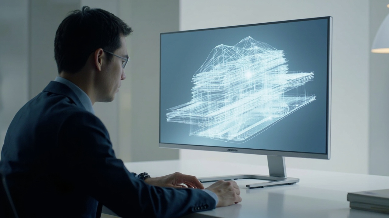
Layer 1: source content carries spatial information
The source must provide more than a flat image. It may contain a left/right stereo pair, multiple camera views, a 3D scene that can be rendered from two viewpoints, or depth information that a supported application can use.
A file extension alone does not prove readiness. A CAD model can contain geometry but still require a stereo-capable viewer. An SBS video already contains two views, but eye order and aspect-ratio handling must be correct. Ordinary 2D media remains 2D unless a separate, validated conversion process exists.
Layer 2: the host application prepares the output
The host layer opens, decodes, renders, or exports the content. Its responsibility may include:
- selecting a stereo camera pair;
- packaging views as SBS or another supported format;
- maintaining application performance at the intended resolution and frame rate;
- preserving scale, labels, and interaction needed by the review task.
A video cable confirms signal transport, not spatial compatibility. The host must deliver the kind of signal the display workflow expects.
Layer 3: display processing maps views to pixels
The display-specific processing layer receives content and, in a dynamic system, viewer-position data. It then maps the left/right information to panel pixels in a pattern that matches the optical layer.
Keeping timing-sensitive mapping inside the display can create a cleaner boundary: the workstation handles the application and the display handles its own spatial presentation. It does not make a heavy source application lightweight. The FPGA rendering-pipeline article explains this boundary in detail.
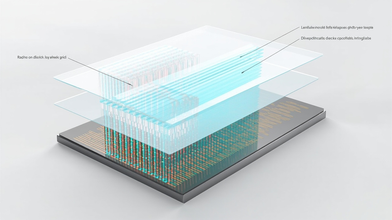
Layer 4: optics direct light toward the eyes
A lenticular layer, parallax barrier, or another directional optical design controls which pixels are visible from each position. Optical alignment, panel pixel density, brightness, coatings, and view separation influence crosstalk and detail.
The optics do not understand the content. They can only direct the pixel pattern they receive. Incorrect mapping or left/right order can therefore produce reversed or unstable depth even when the panel and lens are physically correct.
Layer 5: viewer position closes the system
The final output depends on where the viewer sits or stands. Eye tracking can estimate that position and allow the mapping to follow a primary user, but the practical viewing zone, room lighting, screen height, and posture remain part of the installation.
The operator also belongs in this layer. They choose files, launch the application, switch modes, and decide whether the view supports the task. A technically correct depth effect can still be unhelpful if the content scale, disparity, or user interface does not fit the review.
Diagnose by symptom, layer, and test
| Symptom | Likely layers to check | First test |
|---|---|---|
| image remains flat | source, application, input mode | open a known-good stereo sample through the same path |
| depth is reversed | content packaging, eye order, mapping | swap left/right views |
| ghosting changes with head position | tracking, mapping, optics, room | test slow movement at the specified distance |
| interaction stutters | host rendering or decoding | monitor application performance before changing display settings |
| fine text is hard to read | 2D/3D mode, per-eye detail, scale | compare the exact interface in both modes |
This method avoids replacing hardware when the source is wrong—or rewriting software when room geometry is the cause.
A complete acceptance test
Validate the chain with representative content, the intended workstation, normal room light, and the primary operator. Record the source format, application version, output mode, display mode, viewing distance, and any preparation steps. Then repeat the same test after installation.
For file- and application-level planning, use the spatial content compatibility guide. A spatial display is best treated as a system with explicit interfaces, not as a screen that can repair every upstream input.