
Parallax Barrier Displays: Fit and Trade-Offs
A parallax barrier display creates glasses-free 3D by placing a patterned mask in front of the panel. The mask allows selected pixel columns to reach the left eye and others to reach the right eye. This can produce convincing stereoscopic depth, but it trades some light and spatial resolution for directional view separation.
The architecture is not inherently “good” or “bad.” Its fit depends on viewer position, brightness requirements, pixel density, tracking, and the task being performed.
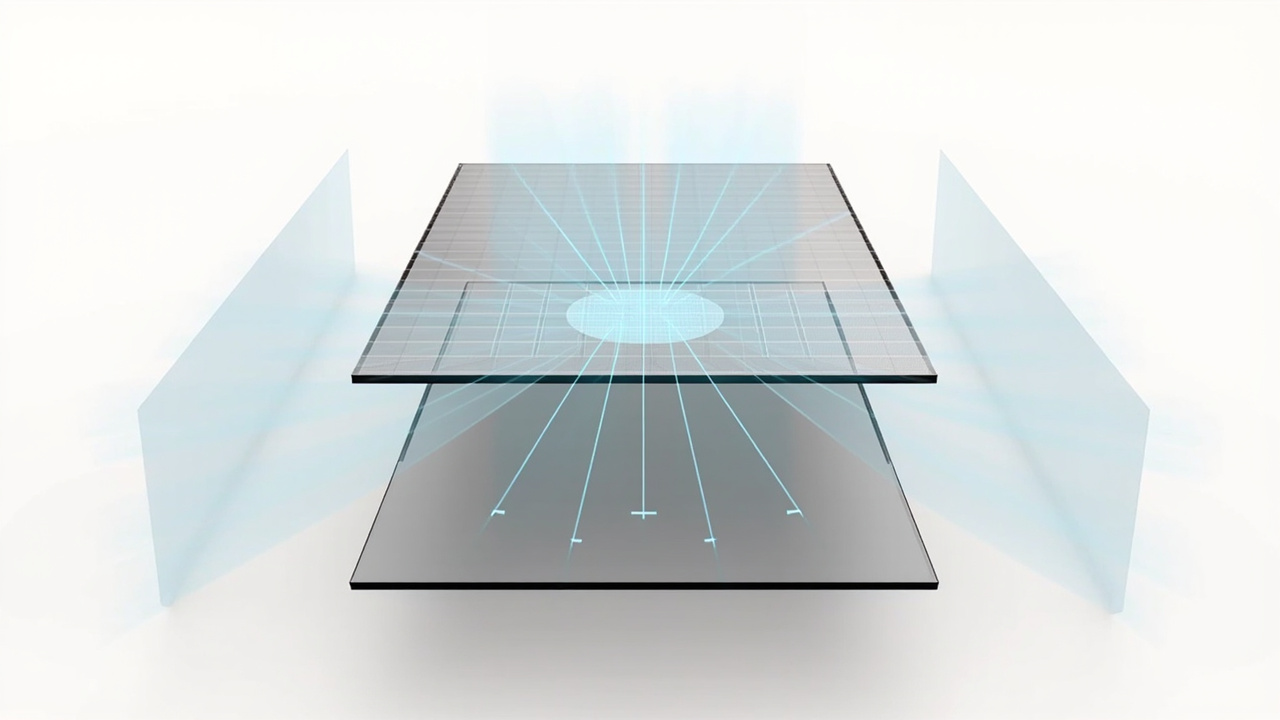
How the barrier creates separate views
The panel contains both eye views in an interlaced pixel pattern. Openings in the barrier control the direction in which those pixels are visible. At the intended position, one eye receives one set and the other eye receives the complementary set.
This is different from content creation. The barrier separates views; it does not create them. A player or application must still supply suitable stereo information, and the mapping must match the optical geometry.
The four trade-offs that matter
Brightness
Because part of the panel light is blocked, perceived brightness can be lower than in normal 2D operation. Panel output, barrier design, room light, and surface reflections determine the real result. Test under the intended ambient conditions rather than in a dark demonstration room only.
Per-eye detail
The left and right views share the panel’s physical pixels. Effective detail per view may therefore be lower than the panel’s headline 2D resolution. Fine text, thin lines, and dense interfaces should be evaluated in both modes.
Viewing zones
Fixed barriers create positions where the views separate correctly and positions where they can reverse or mix. A seated, single-user device can work well with a controlled sweet spot. A moving operator or group audience may expose the limits quickly.
Crosstalk
If the viewer is between zones, the optical layer is misaligned, or the mapping is incorrect, one eye can receive part of the other eye’s view. The result appears as ghosting, soft edges, or unstable depth.
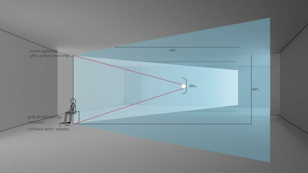
Fixed barrier versus tracked barrier
Eye tracking can make a barrier-based system more flexible by updating the pixel mapping for the primary viewer’s position. It does not eliminate the barrier’s light or resolution trade-offs, and the tracked range remains finite.
When comparing systems, avoid treating “eye tracking” as a complete answer. Test the combined sensing, mapping, panel, and optics while the user leans, sits back, or changes posture. The foundational eye-tracking guide explains that system chain.
Where a parallax barrier can fit
The architecture can be suitable when:
- one primary viewer uses a known desk or kiosk position;
- the room lighting is controlled;
- the content has bold spatial structure rather than tiny stereo detail;
- the display has sufficient native resolution and brightness for the task;
- low-cost or compact construction is more important than a wide viewing area.
It needs closer scrutiny when multiple people expect simultaneous 3D, users move across a wide room, dense 2D work dominates, or the installation cannot control reflections and viewing distance.
Compare architectures by evidence
| Question | Parallax barrier | Lenticular optical layer | Eye-tracked implementation |
|---|---|---|---|
| How are views directed? | patterned apertures | lens array | either optical method plus dynamic mapping |
| Main evaluation risk | light loss and fixed zones | optical alignment and view allocation | tracking-to-display latency and stability |
| Best test | brightness, detail, zone transitions | crosstalk, detail, viewing range | natural movement with real content |
These categories can overlap: an eye-tracked system still uses an optical method to direct light. Product comparison should identify the complete architecture instead of comparing labels alone.
Practical evaluation protocol
- Use representative stereo content with fine edges and moderate depth.
- Confirm left/right order and correct mapping.
- Measure usability at the intended distance and screen height.
- Move slowly across and beyond the expected zone.
- Compare 2D brightness and detail with 3D mode.
- Repeat under real room lighting for a realistic session length.
If the content path itself is uncertain, resolve it with the compatibility guide before judging the optics. The display architecture and the source workflow are separate decisions.